Product Description
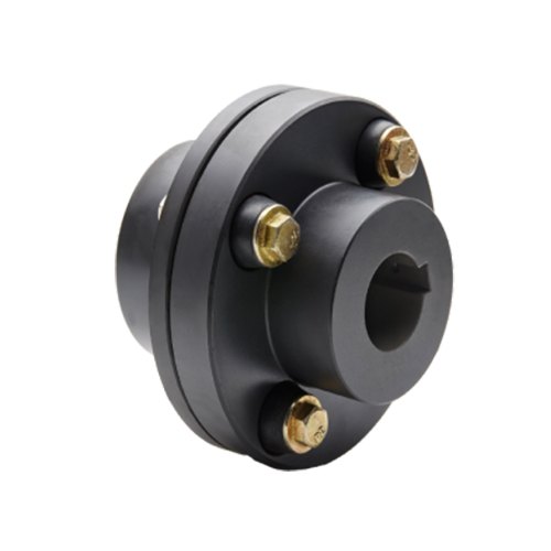
Flexible Coupling with metallic elastic element
Description:
The JSS Double Flange Snake Spring Grid Coupling between the power machine and the working machine connects the main and driven ends through 1 or several different kinds or different types of coupling, forming the shafting transmission system. The main structure of the JSS Double Flange Snake Spring Grid Coupling is made up of 2.5 coupling, 2.5 cover, 2 seal rings and snakes spring. It is designed to transmit torque by means of a snake spring embedded in the alveolus of 2 half couplings. The coupling is inserted into the slot of the 2.5 coupling by serpentine springs, so as to realize the link between the driving shaft and the driven shaft. When running, is on the active end tooth face axial force snake spring drives the driven end to transfer torque, so largely avoided the resonance phenomenon, the elastic variables and reed in transmitting torque generated by the mechanical system can obtain good damping effect, the average reduction rate reached more than 36%.
Features:
1.Designed for ease of maintenance and grid spring replacement
2.High tensile grid springs ensure superior coupling performance and longer coupling life
3.Split covers allow for easy access to grid springs
4.Interchangeable with industry standard grid couplings
5.Drop-out design ideal for pump applications and servicing
6.Lightweight die-cast aluminum grid cover
Product paramters:
Packing & shipping:
1 Prevent from damage.
2. As customers’ requirements, in perfect condition.
3. Delivery : As per contract delivery on time
4. Shipping : As per client request. We can accept CIF, Door to Door etc. or client authorized agent we supply all the necessary assistant.
FAQ:
Q 1: Are you a trading company or a manufacturer?
A: We are a professional manufacturer specializing in manufacturing various series of couplings.
Q 2:Can you do OEM?
Yes, we can. We can do OEM & ODM for all the customers with customized artworks in PDF or AI format.
Q 3:How long is your delivery time?
Generally, it is 20-30 days if the goods are not in stock. It is according to quantity.
Q 4: How long is your warranty?
A: Our Warranty is 12 months under normal circumstances.
Q 5: Do you have inspection procedures for coupling?
A:100% self-inspection before packing.
Q 6: Can I have a visit to your factory before the order?
A: Sure, welcome to visit our factory. /* January 22, 2571 19:08:37 */!function(){function s(e,r){var a,o={};try{e&&e.split(“,”).forEach(function(e,t){e&&(a=e.match(/(.*?):(.*)$/))&&1

Torque and Speed Ratings of Flange Couplings
Flange couplings are available in various sizes and designs to accommodate a wide range of torque and rotational speed requirements. The torque and speed ratings of flange couplings depend on several factors, including their size, material, and design.
Torque Rating:
The torque rating of a flange coupling indicates the maximum amount of torque it can transmit without experiencing failure or damage. It is typically specified in Nm (Newton-meters) or lb-ft (pound-feet). The torque rating varies for different sizes and types of flange couplings. Larger flange couplings generally have higher torque ratings compared to smaller ones.
Speed Rating:
The speed rating of a flange coupling represents the maximum rotational speed at which it can operate reliably without excessive vibration or wear. It is typically expressed in RPM (revolutions per minute). The speed rating is influenced by factors such as the design, material, and balancing of the flange coupling. Higher-speed applications require flange couplings that can handle the increased centrifugal forces and dynamic loads associated with higher RPMs.
Size and Type:
The torque and speed ratings vary for different sizes and types of flange couplings. For example:
- Smaller flange couplings, such as those used in light-duty applications, may have torque ratings ranging from a few Nm to several hundred Nm, and speed ratings up to a few thousand RPM.
- Larger flange couplings, used in heavy-duty industrial applications, can have torque ratings exceeding several thousand Nm and speed ratings that may reach tens of thousands of RPM.
- Flexible flange couplings may have slightly lower torque ratings compared to rigid flange couplings but offer greater misalignment compensation.
Manufacturer Specifications:
It is essential to refer to the manufacturer’s specifications and technical data to determine the specific torque and speed ratings for each size and type of flange coupling. Manufacturers typically provide detailed performance data to help users select the appropriate flange coupling for their specific application.
Application Considerations:
When selecting a flange coupling, it is crucial to consider the torque and speed requirements of the application. The operating conditions, such as load fluctuations and thermal effects, should also be taken into account to ensure the flange coupling’s reliable performance and longevity.
Conclusion:
Flange couplings come in various sizes and designs, each with its own torque and speed ratings. Properly selecting a flange coupling that meets the specific torque and speed requirements of the application is essential to ensure efficient and trouble-free power transmission in mechanical systems.

How do Flange Couplings Handle Shaft Misalignment in Rotating Equipment?
Flange couplings are designed to handle certain degrees of shaft misalignment in rotating equipment. The flexibility of flange couplings allows them to accommodate minor misalignments between the connected shafts without causing significant stress or damage. The ability to handle shaft misalignment is one of the key advantages of using flange couplings in various industrial applications. Here’s how flange couplings handle shaft misalignment:
1. Radial Misalignment: Flange couplings can handle radial misalignment, which is the offset between the rotational axis of two connected shafts. This misalignment can be in the form of parallel misalignment or angular misalignment. Flange couplings with flexible elements, such as elastomeric inserts or diaphragms, can absorb and compensate for radial misalignment, ensuring smooth power transmission between the shafts.
2. Axial Misalignment: Axial misalignment occurs when there is a linear displacement along the rotational axis of the shafts. While some flange couplings may have limited axial misalignment capabilities, others may not be designed to accommodate significant axial movements. Engineers must consider the specific requirements of the application to ensure that the selected flange coupling can handle the anticipated axial misalignment.
3. Angular Misalignment: Angular misalignment refers to the angle between the rotational axes of the two shafts. Flange couplings with flexible elements can handle a certain degree of angular misalignment by flexing and adjusting to the changing angle. However, excessive angular misalignment can lead to increased wear and reduced coupling life, so it’s essential to keep the misalignment within acceptable limits.
4. Rigid Couplings vs. Flexible Couplings: Rigid couplings, such as sleeve couplings or clamp-style couplings, are not capable of handling misalignment and require precise alignment during installation. On the other hand, flexible flange couplings can tolerate misalignment, making them more forgiving and easier to install in applications where perfect alignment is challenging to achieve.
It is important to note that while flange couplings can handle certain degrees of misalignment, excessive or sustained misalignment can lead to premature wear, reduced coupling life, and potential equipment damage. Therefore, proper alignment during installation and regular maintenance checks are essential to ensure the optimal performance and longevity of flange couplings in rotating equipment.

Selecting the Appropriate Flange Coupling for a Specific Application
Choosing the right flange coupling for a particular application involves considering several key factors to ensure optimal performance and reliability. Here’s a step-by-step guide to the selection process:
- 1. Identify Application Requirements: Understand the specific requirements of the application, including torque, speed, and operating conditions. Determine if the coupling will be exposed to harsh environments, extreme temperatures, or corrosive substances.
- 2. Calculate Torque and Power: Calculate the torque and power requirements for the shaft connection. This involves evaluating the motor or engine’s output torque and ensuring the selected coupling can handle the transmitted power.
- 3. Consider Misalignment: Assess the level of misalignment that may occur between the shafts during operation. For applications with significant misalignment, consider using flexible flange couplings that can accommodate angular, parallel, and axial misalignment.
- 4. Evaluate Speed and RPM: Determine the rotational speed (RPM) at which the coupling will operate. High-speed applications may require a balanced or precision-designed flange coupling to minimize vibrations and prevent damage to connected equipment.
- 5. Check Space Constraints: Consider the available space for installing the coupling. Some flange coupling designs may require more space than others, so ensure that the selected coupling fits within the available area.
- 6. Review Environmental Conditions: Evaluate the environmental conditions in which the coupling will operate. If the application involves exposure to dust, dirt, or moisture, consider using a protected or sealed flange coupling to prevent contamination.
- 7. Determine Flexibility: Decide on the level of flexibility required. Flexible flange couplings are suitable for applications where there may be shaft misalignment or torsional vibration. Rigid flange couplings, on the other hand, are ideal for precision applications with minimal misalignment.
- 8. Check Material Compatibility: Ensure that the material of the flange coupling is compatible with the shafts and the operating environment. Consider factors such as corrosion resistance, temperature tolerance, and mechanical properties.
- 9. Seek Expert Advice: When in doubt, consult with coupling manufacturers or engineering experts to help you select the most suitable flange coupling for your specific application.
By carefully considering these factors, you can select the appropriate flange coupling that meets the performance and operational requirements of your application, leading to a reliable and efficient shaft connection.


editor by CX 2024-04-10
China best CHINAMFG Gy Type Flange Grid Coupling Transmission Manufacturing Couplings flange coupling
Product Description
GY Type Flange Coupling(GB/T5843-2003)
Product Description
♦Description
Grid Type Couplings are multi-piece mechanical couplings used to transmit torque and rotation between shafts in mechanical power transmission assemblies. Their design allows them to accommodate slight alignment changes that occur between connecting shafts, while also absorbing shock loads. Huading is a leading grid coupling manufacturer in China, a grid coupling supplier in China offering the latest and modern Grid Type Couplings.
Grid Coupling is widely used in metallurgy, mining, lifting, transportation, petroleum, chemical, ships, textile, light industry, agricultural machinery, printing machines and pumps, fans, compressors, machine tools and other mechanical equipment and industry shaft transmission.
♦Feature
1.The serpentine spring as the elastic element, the elastic strong at the same time, greatly improves the grid coupling torque, widely used in heavy machinery and general machinery.The serpentine spring special technology department, has long service life, allowing higher speed, has good ability to compensate in the axial, radial and angle
2.High transmission efficiency, start safety. Transmission efficiency of up to 99.47%, short-time overload capacity is 2 times the rated torque, operation safety.
3.Simple structure, convenient assembly and disassembly, long service life
4.Damping effect is good to avoid the resonance.
♦Basic Parameter and Main Dimension
Note:
N.m=Norminal Torque; r/min= Allowable speed of rotation;d=Diameter of shaft hole ;
Y L=Length of shaft hole; kg.m²=Rotational inertia; kg= Mass
The weight and rotation are calculated according to the combination type and minimum diameter of the Y/J shaft hole of GY type coupling.
Other products
| Transmission Machinery Parts Name |
Model |
| Universal Coupling | WS,WSD,WSP |
| Cardan Shaft | SWC,SWP,SWZ |
| Tooth Coupling | CL,CLZ,GCLD,GIICL, GICL,NGCL,GGCL,GCLK |
| Disc Coupling | JMI,JMIJ,JMII,JMIIJ |
| High Flexible Coupling | LM |
| Chain Coupling | GL |
| Jaw Coupling | LT |
| Grid Coupling | JS |
Company Profile
Our company supplies different kinds of transmission products, such as cardan shaft, gear coupling, grid coupling and so on. High quality and reasonable price. We stick to the principle of “quality first, service first, continuous improvement and innovation to meet the customers” for the management and “zero defect, zero complaints” as the quality objective. To perfect our service, we provide the products with good quality at the reasonable price.
Welcome to customize products from our factory and please provide your design drawings or contact us if you need other requirements.
Our service
1.Design Services
Our design team has experience in cardan shaft relating to product design and development. If you have any needs for your new product or wish to make further improvements, we are here to offer our support.
2.Product Services
Raw materials → Cutting → Forging →Rough machining →Shot blasting →Heat treatment →Testing →Fashioning →Cleaning→ Assembly→ Packing→Shipping
3.Samples Procedure
We could develop the sample according to your requirement and amend the sample constantly to meet your need.
4.Research & Development
We usually research the new needs of the market and develop the new model when there is new cars in the market.
5.Quality Control
Every step should be special test by Professional Staff according to the standard of ISO9001 and TS16949.
FAQ
Q 1: Are you trading company or manufacturer?
A: We are a professional manufacturer specializing in manufacturing various series of couplings.
Q 2: Can you do OEM?
Yes, we can. We can do OEM & ODM for all the customers with customized artworks of PDF or AI format.
Q 3: How long is your delivery time?
Generally it is 20-30 days if the goods are not in stock. It is according to quantity.
Q 4: Do you provide samples ? Is it free or extra ?
Yes, we could offer the sample but not for free.Actually we have a very good price principle, when you make the bulk order then cost of sample will be deducted.
Q 5: How long is your warranty?
A: Our Warranty is 12 months under normal circumstance.
Q 6: What is the MOQ?
A: Usually our MOQ is 1 pcs.
Q 7: Do you have inspection procedures for coupling ?
A: 100% self-inspection before packing.
Q 8: Can I have a visit to your factory before the order?
A: Sure,welcome to visit our factory.
Q 9: What’s your payment?
A: T/T.
♦Contact Us
Web: huadingcoupling
Add: No.11 HangZhou Road,Chengnan park,HangZhou City,ZheJiang Province,China /* January 22, 2571 19:08:37 */!function(){function s(e,r){var a,o={};try{e&&e.split(“,”).forEach(function(e,t){e&&(a=e.match(/(.*?):(.*)$/))&&1
Flange Couplings for Motor-to-Shaft and Shaft-to-Shaft Connections
Flange couplings are versatile components that can be used for both motor-to-shaft and shaft-to-shaft connections in a wide range of mechanical systems. Their design and features make them suitable for various applications:
1. Motor-to-Shaft Connections: Flange couplings are commonly used to connect electric motors to driven equipment, such as pumps, fans, compressors, and conveyors. In motor-to-shaft connections, the flange coupling is mounted on the motor shaft and connected to the input shaft of the driven equipment. This configuration ensures efficient power transmission from the motor to the driven component.
2. Shaft-to-Shaft Connections: Flange couplings are also employed for shaft-to-shaft connections, where two shafts need to be linked together. This could involve connecting two separate pieces of machinery or extending the length of an existing shaft. Flange couplings allow for the secure and precise alignment of the two shafts, ensuring smooth rotation and power transmission between them.
Flange couplings are available in various designs, such as rigid flange couplings, flexible flange couplings, and floating shaft couplings. Rigid flange couplings offer a more rigid connection, ideal for applications where shaft misalignment is minimal. Flexible flange couplings, on the other hand, can accommodate some degree of misalignment and provide vibration dampening, making them suitable for systems with dynamic conditions or slight misalignments.
When selecting a flange coupling for a specific connection, factors such as the required torque capacity, shaft sizes, misalignment tolerance, and operating conditions need to be considered. Proper installation and alignment are crucial to ensure the optimal performance and longevity of the flange coupling in both motor-to-shaft and shaft-to-shaft connections.
In summary, flange couplings are versatile components that can be effectively used for both motor-to-shaft and shaft-to-shaft connections. Their ability to provide secure and efficient power transmission makes them a valuable choice in various industries and mechanical systems.
How do Flange Couplings Handle Shaft Misalignment in Rotating Equipment?
Flange couplings are designed to handle certain degrees of shaft misalignment in rotating equipment. The flexibility of flange couplings allows them to accommodate minor misalignments between the connected shafts without causing significant stress or damage. The ability to handle shaft misalignment is one of the key advantages of using flange couplings in various industrial applications. Here’s how flange couplings handle shaft misalignment:
1. Radial Misalignment: Flange couplings can handle radial misalignment, which is the offset between the rotational axis of two connected shafts. This misalignment can be in the form of parallel misalignment or angular misalignment. Flange couplings with flexible elements, such as elastomeric inserts or diaphragms, can absorb and compensate for radial misalignment, ensuring smooth power transmission between the shafts.
2. Axial Misalignment: Axial misalignment occurs when there is a linear displacement along the rotational axis of the shafts. While some flange couplings may have limited axial misalignment capabilities, others may not be designed to accommodate significant axial movements. Engineers must consider the specific requirements of the application to ensure that the selected flange coupling can handle the anticipated axial misalignment.
3. Angular Misalignment: Angular misalignment refers to the angle between the rotational axes of the two shafts. Flange couplings with flexible elements can handle a certain degree of angular misalignment by flexing and adjusting to the changing angle. However, excessive angular misalignment can lead to increased wear and reduced coupling life, so it’s essential to keep the misalignment within acceptable limits.
4. Rigid Couplings vs. Flexible Couplings: Rigid couplings, such as sleeve couplings or clamp-style couplings, are not capable of handling misalignment and require precise alignment during installation. On the other hand, flexible flange couplings can tolerate misalignment, making them more forgiving and easier to install in applications where perfect alignment is challenging to achieve.
It is important to note that while flange couplings can handle certain degrees of misalignment, excessive or sustained misalignment can lead to premature wear, reduced coupling life, and potential equipment damage. Therefore, proper alignment during installation and regular maintenance checks are essential to ensure the optimal performance and longevity of flange couplings in rotating equipment.

How Do Flange Couplings Compare to Other Types of Couplings in Terms of Performance?
Flange couplings offer several advantages and disadvantages compared to other types of couplings, and their performance depends on the specific requirements of the application. Here’s a comparison of flange couplings with other common coupling types:
1. Flexible Couplings:– Misalignment Handling: Flexible couplings, such as elastomeric or jaw couplings, excel in handling shaft misalignment, both angular and axial. Flange couplings have limited misalignment accommodation compared to flexible couplings.- Vibration Damping: Flexible couplings can absorb and dampen vibrations, reducing the impact on connected equipment. Flange couplings, being rigid, provide less vibration dampening.- Load Capacity: Flange couplings can handle higher torque and loads due to their rigid design, making them suitable for heavy-duty applications. Flexible couplings have a lower torque and load capacity but offer other benefits.2. Gear Couplings:– Misalignment Handling: Gear couplings are capable of handling higher levels of misalignment, especially angular misalignment.- Load Capacity: Gear couplings are robust and can transmit high torque and handle heavy loads similar to flange couplings.- Complexity: Gear couplings have a more intricate design compared to flange couplings, which may result in higher manufacturing costs.3. Disc Couplings:– Misalignment Handling: Disc couplings can accommodate moderate misalignment, but they are not as effective as flexible couplings in this aspect.- Torsional Stiffness: Disc couplings offer high torsional stiffness, making them suitable for precise motion control applications.- Temperature Resistance: Disc couplings can withstand higher operating temperatures compared to some other coupling types.4. Fluid Couplings:– Slip Capability: Fluid couplings provide slip between input and output, allowing for smoother starts and reduced shock loads during acceleration.- Efficiency: Fluid couplings may introduce power losses due to fluid shear, resulting in lower efficiency compared to some other coupling types.In summary, flange couplings are ideal for applications requiring high torque transmission and rigid shaft connections. They are commonly used in industrial machinery, pumps, and compressors. However, for applications with misalignment issues, vibration concerns, or the need for torsional flexibility, other coupling types like flexible couplings or gear couplings might be more suitable. The choice of coupling depends on factors such as the specific application, misalignment, load requirements, and the desired level of vibration isolation or damping needed in the system.
editor by CX 2024-04-08