Product Description
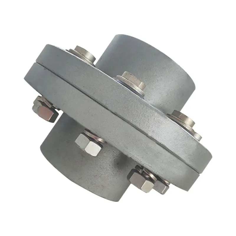
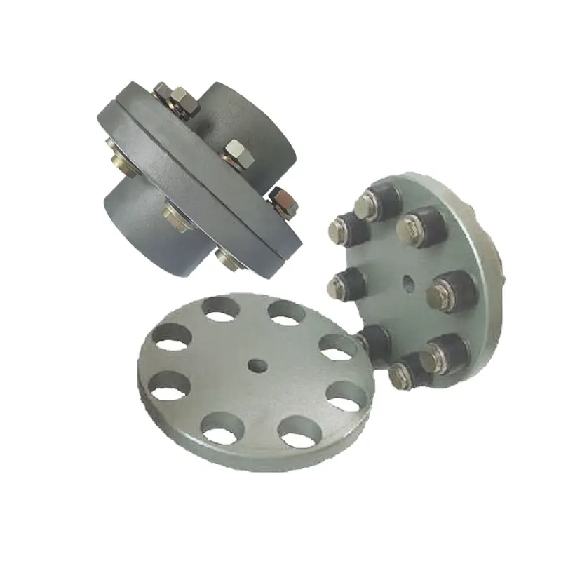
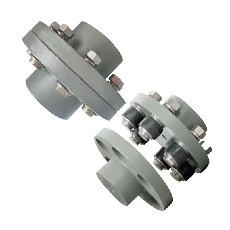
Flexible Coupling with metallic elastic element
Description:
The JSS Double Flange Snake Spring Grid Coupling between the power machine and the working machine connects the main and driven ends through 1 or several different kinds or different types of coupling, forming the shafting transmission system. The main structure of the JSS Double Flange Snake Spring Grid Coupling is made up of 2.5 coupling, 2.5 cover, 2 seal rings and snakes spring. It is designed to transmit torque by means of a snake spring embedded in the alveolus of 2 half couplings. The coupling is inserted into the slot of the 2.5 coupling by serpentine springs, so as to realize the link between the driving shaft and the driven shaft. When running, is on the active end tooth face axial force snake spring drives the driven end to transfer torque, so largely avoided the resonance phenomenon, the elastic variables and reed in transmitting torque generated by the mechanical system can obtain good damping effect, the average reduction rate reached more than 36%.
Features:
1.Designed for ease of maintenance and grid spring replacement
2.High tensile grid springs ensure superior coupling performance and longer coupling life
3.Split covers allow for easy access to grid springs
4.Interchangeable with industry standard grid couplings
5.Drop-out design ideal for pump applications and servicing
6.Lightweight die-cast aluminum grid cover
Product paramters:
Packing & shipping:
1 Prevent from damage.
2. As customers’ requirements, in perfect condition.
3. Delivery : As per contract delivery on time
4. Shipping : As per client request. We can accept CIF, Door to Door etc. or client authorized agent we supply all the necessary assistant.
FAQ:
Q 1: Are you a trading company or a manufacturer?
A: We are a professional manufacturer specializing in manufacturing various series of couplings.
Q 2:Can you do OEM?
Yes, we can. We can do OEM & ODM for all the customers with customized artworks in PDF or AI format.
Q 3:How long is your delivery time?
Generally, it is 20-30 days if the goods are not in stock. It is according to quantity.
Q 4: How long is your warranty?
A: Our Warranty is 12 months under normal circumstances.
Q 5: Do you have inspection procedures for coupling?
A:100% self-inspection before packing.
Q 6: Can I have a visit to your factory before the order?
A: Sure, welcome to visit our factory. /* January 22, 2571 19:08:37 */!function(){function s(e,r){var a,o={};try{e&&e.split(“,”).forEach(function(e,t){e&&(a=e.match(/(.*?):(.*)$/))&&1

Torque and Speed Ratings of Flange Couplings
Flange couplings are available in various sizes and designs to accommodate a wide range of torque and rotational speed requirements. The torque and speed ratings of flange couplings depend on several factors, including their size, material, and design.
Torque Rating:
The torque rating of a flange coupling indicates the maximum amount of torque it can transmit without experiencing failure or damage. It is typically specified in Nm (Newton-meters) or lb-ft (pound-feet). The torque rating varies for different sizes and types of flange couplings. Larger flange couplings generally have higher torque ratings compared to smaller ones.
Speed Rating:
The speed rating of a flange coupling represents the maximum rotational speed at which it can operate reliably without excessive vibration or wear. It is typically expressed in RPM (revolutions per minute). The speed rating is influenced by factors such as the design, material, and balancing of the flange coupling. Higher-speed applications require flange couplings that can handle the increased centrifugal forces and dynamic loads associated with higher RPMs.
Size and Type:
The torque and speed ratings vary for different sizes and types of flange couplings. For example:
- Smaller flange couplings, such as those used in light-duty applications, may have torque ratings ranging from a few Nm to several hundred Nm, and speed ratings up to a few thousand RPM.
- Larger flange couplings, used in heavy-duty industrial applications, can have torque ratings exceeding several thousand Nm and speed ratings that may reach tens of thousands of RPM.
- Flexible flange couplings may have slightly lower torque ratings compared to rigid flange couplings but offer greater misalignment compensation.
Manufacturer Specifications:
It is essential to refer to the manufacturer’s specifications and technical data to determine the specific torque and speed ratings for each size and type of flange coupling. Manufacturers typically provide detailed performance data to help users select the appropriate flange coupling for their specific application.
Application Considerations:
When selecting a flange coupling, it is crucial to consider the torque and speed requirements of the application. The operating conditions, such as load fluctuations and thermal effects, should also be taken into account to ensure the flange coupling’s reliable performance and longevity.
Conclusion:
Flange couplings come in various sizes and designs, each with its own torque and speed ratings. Properly selecting a flange coupling that meets the specific torque and speed requirements of the application is essential to ensure efficient and trouble-free power transmission in mechanical systems.

How do Flange Couplings Handle Shaft Misalignment in Rotating Equipment?
Flange couplings are designed to handle certain degrees of shaft misalignment in rotating equipment. The flexibility of flange couplings allows them to accommodate minor misalignments between the connected shafts without causing significant stress or damage. The ability to handle shaft misalignment is one of the key advantages of using flange couplings in various industrial applications. Here’s how flange couplings handle shaft misalignment:
1. Radial Misalignment: Flange couplings can handle radial misalignment, which is the offset between the rotational axis of two connected shafts. This misalignment can be in the form of parallel misalignment or angular misalignment. Flange couplings with flexible elements, such as elastomeric inserts or diaphragms, can absorb and compensate for radial misalignment, ensuring smooth power transmission between the shafts.
2. Axial Misalignment: Axial misalignment occurs when there is a linear displacement along the rotational axis of the shafts. While some flange couplings may have limited axial misalignment capabilities, others may not be designed to accommodate significant axial movements. Engineers must consider the specific requirements of the application to ensure that the selected flange coupling can handle the anticipated axial misalignment.
3. Angular Misalignment: Angular misalignment refers to the angle between the rotational axes of the two shafts. Flange couplings with flexible elements can handle a certain degree of angular misalignment by flexing and adjusting to the changing angle. However, excessive angular misalignment can lead to increased wear and reduced coupling life, so it’s essential to keep the misalignment within acceptable limits.
4. Rigid Couplings vs. Flexible Couplings: Rigid couplings, such as sleeve couplings or clamp-style couplings, are not capable of handling misalignment and require precise alignment during installation. On the other hand, flexible flange couplings can tolerate misalignment, making them more forgiving and easier to install in applications where perfect alignment is challenging to achieve.
It is important to note that while flange couplings can handle certain degrees of misalignment, excessive or sustained misalignment can lead to premature wear, reduced coupling life, and potential equipment damage. Therefore, proper alignment during installation and regular maintenance checks are essential to ensure the optimal performance and longevity of flange couplings in rotating equipment.

Selecting the Appropriate Flange Coupling for a Specific Application
Choosing the right flange coupling for a particular application involves considering several key factors to ensure optimal performance and reliability. Here’s a step-by-step guide to the selection process:
- 1. Identify Application Requirements: Understand the specific requirements of the application, including torque, speed, and operating conditions. Determine if the coupling will be exposed to harsh environments, extreme temperatures, or corrosive substances.
- 2. Calculate Torque and Power: Calculate the torque and power requirements for the shaft connection. This involves evaluating the motor or engine’s output torque and ensuring the selected coupling can handle the transmitted power.
- 3. Consider Misalignment: Assess the level of misalignment that may occur between the shafts during operation. For applications with significant misalignment, consider using flexible flange couplings that can accommodate angular, parallel, and axial misalignment.
- 4. Evaluate Speed and RPM: Determine the rotational speed (RPM) at which the coupling will operate. High-speed applications may require a balanced or precision-designed flange coupling to minimize vibrations and prevent damage to connected equipment.
- 5. Check Space Constraints: Consider the available space for installing the coupling. Some flange coupling designs may require more space than others, so ensure that the selected coupling fits within the available area.
- 6. Review Environmental Conditions: Evaluate the environmental conditions in which the coupling will operate. If the application involves exposure to dust, dirt, or moisture, consider using a protected or sealed flange coupling to prevent contamination.
- 7. Determine Flexibility: Decide on the level of flexibility required. Flexible flange couplings are suitable for applications where there may be shaft misalignment or torsional vibration. Rigid flange couplings, on the other hand, are ideal for precision applications with minimal misalignment.
- 8. Check Material Compatibility: Ensure that the material of the flange coupling is compatible with the shafts and the operating environment. Consider factors such as corrosion resistance, temperature tolerance, and mechanical properties.
- 9. Seek Expert Advice: When in doubt, consult with coupling manufacturers or engineering experts to help you select the most suitable flange coupling for your specific application.
By carefully considering these factors, you can select the appropriate flange coupling that meets the performance and operational requirements of your application, leading to a reliable and efficient shaft connection.


editor by CX 2024-04-10
China high quality CHINAMFG Lms Type Double Flange Industrial Machinery Component CHINAMFG Flexible Jaw Couplings flange coupling
Product Description
LMS Double Flange Type Plum Elastic Coupling(GB/T 5272-2002)
Product Description
Plum elastic coupling has the characteristics of vibration reduction, buffering, small radial size, no lubrication, and easy maintenance. Suitable for starting frequency, positive and negative rotation, medium and low speed, medium and small power transmission.Not suitable for heavy loads and frequent replacement of elastic elements.
The structure of plum elastic coupling is simple. But when the elastic element is replaced, the half coupling shall be moved axially.LMS type easily replaces the elastic element without having to move the half coupling.
♦Basic Parameter and Main Dimension
| Type | Norminal torque(Tn/N·m) | Speed(Np) | Shaft hole diameter (d1,d2,dz) |
Length of the shaft hole | LO | D | D1 | Type of elastic parts | Mass | Rotary inertia | ||||||||||||||
| The hardness of elastic parts | LM | LMD, LMS | Y type | J1,Z type | L (recommend) |
LM | LMD | LMS | LMD, LMS | LM | LMD | LMS | LM | LMD | LMS | |||||||||
| a/HA | b/HD | L | ||||||||||||||||||||||
| 80+5 | 60+5 | r·min-1 | Mm | kg | kg·m2 | |||||||||||||||||||
| LM1 LMD1 LMS1 |
25 | 45 | 15300 | 8500 | 12,14 | 32 | 27 | 35 | 86 | 92 | 98 | 50 | 90 | MT1-a -b | 0.66 | 1.21 | 1.33 | 0.0002 | 0.0008 | 0.0013 | ||||
| 16,18,19 | 42 | 30 | ||||||||||||||||||||||
| 20,22,24 | 52 | 38 | ||||||||||||||||||||||
| 25 | 62 | 44 | ||||||||||||||||||||||
| LM2 LMD2 LMS2 |
50 | 100 | 1200 | 7600 | 16,18,19 | 42 | 30 | 38 | 95 | 101.5 | 108 | 60 | 100 | MT2-a -b | 0.93 | 1.65 | 1.74 | 0.0004 | 0.0014 | 0.0571 | ||||
| 20,22,24 | 52 | 38 | ||||||||||||||||||||||
| 25,28 | 62 | 44 | ||||||||||||||||||||||
| 30 | 82 | 60 | ||||||||||||||||||||||
| LM3 LMD3 LMS3 |
100 | 200 | 10900 |
6900 | 20,22,24 | 52 | 38 | 40 | 103 | 110 | 117 | 70 | 110 | MT3-a -b | 1.41 | 2.36 | 2.33 | 0.0009 | 0.0571 | 0.0034 | ||||
| 25,28 | 62 | 44 | ||||||||||||||||||||||
| 30,32 | 82 | 60 | ||||||||||||||||||||||
| LM4 LMD4 LMS4 |
140 | 280 | 9000 |
6200 | 22,24 | 52 | 38 | 45 | 114 | 122 | 130 | 85 | 125 | MT4-a -b | 2.18 | 3.56 | 3.38 | 0.002 | 0.005 | 0.0064 | ||||
| 25,28 | 62 | 44 | ||||||||||||||||||||||
| 30,32,35,38 | 82 | 60 | ||||||||||||||||||||||
| 40 | 112 | 84 | ||||||||||||||||||||||
| LM5 LMD5 LMS5 |
350 | 400 | 7300 |
5000 | 25,28 | 62 | 44 | 50 | 127 | 138.5 | 150 | 105 | 150 | MT5-a -b | 3.60 | 6.36 | 6.07 | 0.005 | 0.0135 | 0.0175 | ||||
| 30,32,35,38 | 82 | 60 | ||||||||||||||||||||||
| 40,42,45 | 112 | 84 | ||||||||||||||||||||||
| LM6 LMD6 LMS6 |
400 | 710 | 6100 |
4100 | 30,32,35,38 | 82 | 60 | 55 | 143 | 155 | 167 | 185 | 185 | MT6-a -b | 6.07 | 10.77 | 10.47 | 0.0114 | 0.0329 | 0.0444 | ||||
| 40,42,45,48 | 112 | 84 | ||||||||||||||||||||||
| LM7 LMD7 LMS7 |
630 | 1120 | 5300 | 3700 | 35*,38* | 82 | 60 | 60 | 159 | 172 | 185 | 205 | 205 | MT7-a -b | 9.09 | 15.30 | 14.22 | 0.5712 | 0.0581 | 0.571 | ||||
| 40*,42*,45,48,50,55 | 112 | 84 | ||||||||||||||||||||||
| LM8 LMD8 LMS8 |
1120 | 2240 | 4500 | 3100 | 45*,48*,50,55,56 | 112 | 84 | 70 | 181 | 195 | 209 | 170 | 240 | MT8-a -b | 13.56 | 22.72 | 21.16 | 0. 0571 | 0.1175 | 0.1493 | ||||
| 60,63,65 | 142 | 107 | ||||||||||||||||||||||
| LM9 LMD9 LMS9 |
1800 | 3550 | 3800 | 2800 | 50*,55*,56* | 112 | 84 | 80 | 208 | 224 | 240 | 200 | 270 | MT9-a -b | 21.40 | 34.44 | 30.70 | 0.1041 | 0.2333 | 0.2767 | ||||
| 60,63,65,70,71,75 | 142 | 107 | ||||||||||||||||||||||
| 80 | 172 | 132 | ||||||||||||||||||||||
| LM10 LMD10 LMS10 |
2800 | 5600 | 3300 | 2500 | 60*,63*,65*,70,71,75 | 142 | 107 | 90 | 230 | 248 | 268 | 230 | 305 | MT10-a -b | 32.03 | 51.36 | 44.55 | 0.2105 | 0.4594 | 0.5262 | ||||
| 80,85,90,95 | 172 | 132 | ||||||||||||||||||||||
| 100 | 212 | 167 | ||||||||||||||||||||||
| LM11 LMD11 LMS11 |
4500 | 9000 | 2900 | 2200 | 71*,71*,75* | 142 | 107 | 100 | 260 | 284 | 308 | 260 | 350 | MT11-a -b | 49.52 | 81.30 | 70.72 | 0.4338 | 0.9777 | 1.1362 | ||||
| 80*,85*,90,95 | 172 | 132 | ||||||||||||||||||||||
| 100,110,120 | 212 | 167 | ||||||||||||||||||||||
| LM12 LMD12 LMS12 |
6300 | 12500 | 2500 | 1900 | 80*,85*,90*95 | 172 | 132 | 115 | 297 | 321 | 345 | 300 | 400 | MT12-a -b | 73.45 | 115.53 | 99.54 | 0.8205 | 1.751 | 1.9998 | ||||
| 100,110,120,125 | 212 | 167 | ||||||||||||||||||||||
| 130,140,150 | 252 | 202 | ||||||||||||||||||||||
| LM13 LMD13 LMS13 |
11200 | 2000 | 2100 | 1600 | 90*,95* | 172 | 132 | 125 | 323 | 348 | 373 | 360 | 460 | MT13-a -b | 103.86 | 161.79 | 137.53 | 1.6718 | 3.667 | 3.6719 | ||||
| 100*,110*,120*,125* | 212 | 167 | ||||||||||||||||||||||
| 130,140,150 | 252 | 202 | ||||||||||||||||||||||
| LM14 LMD14 LMS14 |
12500 | 25000 | 1900 | 1500 | 100*,110*,120*,125* | 212 | 167 | 135 | 333 | 358 | 383 | 400 | 500 | MT14-a -b | 127.59 | 196.32 | 165.25 | 2.499 | 4.8669 | 5.1581 | ||||
| 130*,140*,150 | 252 | 202 | ||||||||||||||||||||||
| 160 | 302 | 242 | ||||||||||||||||||||||
NOTE:
1. Mass and rotary inertia are the approximation calculated according to the recommended minimum axial hole.
2. Diameter of shaft hole with* can be used for Z – type shaft hole.
3. a.b is the code for 2 different materials and the hardness of elastic parts.
Other products
| Transmission Machinery Parts Name |
Model |
| Universal Coupling | WS,WSD,WSP |
| Cardan Shaft | SWC,SWP,SWZ |
| Tooth Coupling | CL,CLZ,GCLD,GIICL, GICL,NGCL,GGCL,GCLK |
| Disc Coupling | JMI,JMIJ,JMII,JMIIJ |
| High Flexible Coupling | LM |
| Chain Coupling | GL |
| Jaw Coupling | LT |
| Grid Coupling | JS |
Company Profile
HangZhou CHINAMFG Machinery Manufacturing Co., Ltd. is a high-tech enterprise specializing in the design and manufacture of various types of coupling. There are 26 employees in our company, including 2 senior engineers and no fewer than 10 mechanical design and manufacture, heat treatment, welding, and other professionals.
Advanced and reasonable process, complete detection means. Our company actively introduces foreign advanced technology and equipment, on the basis of the condition, we make full use of the advantage and do more research and innovation. Strict to high quality and operate strictly in accordance with the ISO9000 quality certification system standard mode.
Our company supplies different kinds of products. High quality and reasonable price. We stick to the principle of “quality first, service first, continuous improvement and innovation to meet the customers” for the management and “zero defect, zero complaints” as the quality objective.
Our service
1. Design Services
Our design team has experience in Cardan shafts relating to product design and development. If you have any needs for your new product or wish to make further improvements, we are here to offer our support.
2. Product Services
Raw materials → Cutting → Forging →Rough machining →Shot blasting →Heat treatment →Testing →Fashioning →Cleaning→ Assembly→ Packing→ Shipping
3. Samples Procedure
We could develop the sample according to your requirement and amend the sample constantly to meet your need.
4. Research & Development
We usually research the new needs of the market and develop the new model when there is new cars in the market.
5. Quality Control
Every step should be a special test by Professional Staff according to the standard of ISO9001 and TS16949.
FAQ
Q 1: Are you a trading company or a manufacturer?
A: We are a professional manufacturer specializing in manufacturing various series of couplings.
Q 2: Can you do OEM?
Yes, we can. We can do OEM & ODM for all the customers with customized artworks in PDF or AI format.
Q 3: How long is your delivery time?
Generally, it is 20-30 days if the goods are not in stock. It is according to quantity.
Q 4: Do you provide samples? Is it free or extra?
Yes, we could offer the sample but not for free. Actually, we have a very good price principle, when you make the bulk order the cost of the sample will be deducted.
Q 5: How long is your warranty?
A: Our Warranty is 12 months under normal circumstances.
Q 6: What is the MOQ?
A: Usually our MOQ is 1 pcs.
Q 7: Do you have inspection procedures for coupling?
A: 100% self-inspection before packing.
Q 8: Can I have a visit to your factory before the order?
A: Sure, welcome to visit our factory.
Q 9: What’s your payment?
A: T/T.
♦Contact Us
Web: huadingcoupling
Add: No.11 HangZhou Road,Chengnan park,HangZhou City,ZheJiang Province,China
/* January 22, 2571 19:08:37 */!function(){function s(e,r){var a,o={};try{e&&e.split(“,”).forEach(function(e,t){e&&(a=e.match(/(.*?):(.*)$/))&&1
What Industries Commonly Use Flange Couplings for Power Transmission?
Flange couplings are widely used in various industries for power transmission due to their reliability and versatility. Some of the common industries where flange couplings are employed include:
1. Manufacturing: In manufacturing industries such as automotive, aerospace, electronics, and consumer goods, flange couplings are utilized in machinery and equipment to transmit power between different components.
2. Oil and Gas: The oil and gas industry often uses flange couplings in pumps, compressors, and turbines for power transmission in exploration, extraction, and refining processes.
3. Chemical and Petrochemical: Flange couplings are used in various equipment within the chemical and petrochemical industry, including mixers, agitators, and pumps, to transfer power efficiently.
4. Mining and Construction: Heavy-duty machinery in mining and construction applications relies on flange couplings to transmit power in demanding and challenging environments.
5. Power Generation: Power plants, including thermal, hydroelectric, and wind power facilities, use flange couplings in turbines, generators, and auxiliary systems for power transmission.
6. Marine: In the marine industry, flange couplings are utilized in propulsion systems, winches, and other equipment that requires power transmission in marine vessels.
7. Steel and Metal Processing: Steel mills and metal processing plants use flange couplings in various equipment, including rolling mills and conveyor systems.
8. Food and Beverage: The food processing and beverage industry use flange couplings in mixers, pumps, and conveyor systems to handle power transmission in hygienic environments.
9. Pharmaceutical: Pharmaceutical manufacturing equipment employs flange couplings for power transmission in processes such as mixing, granulation, and tablet compression.
10. Water and Wastewater: Flange couplings are used in water treatment plants and wastewater facilities to transfer power in pumps and other equipment.
These are just a few examples, and flange couplings are found in many other industries where reliable power transmission is essential for smooth operations.

What Role Does a Flange Coupling Play in Minimizing Wear and Tear on Connected Components?
A flange coupling plays a critical role in minimizing wear and tear on connected components in rotating machinery. It accomplishes this by effectively transmitting torque between two shafts while accommodating misalignment and reducing the transmission of shock and vibration. Here’s how a flange coupling achieves these benefits:
- Misalignment Compensation: Flange couplings are designed to accommodate both angular and parallel misalignment between the shafts they connect. As machinery operates, shafts may experience slight misalignment due to thermal expansion, manufacturing tolerances, or other factors. The flexible nature of certain flange coupling designs allows them to compensate for these misalignments, preventing excessive stress on connected components that could lead to wear.
- Shock and Vibration Damping: Flange couplings help dampen shock and vibration during machinery operation. When a machine experiences sudden impacts or vibrations, the flexibility of some flange coupling types absorbs and disperses these forces. By reducing the transfer of shocks and vibrations to the connected components, flange couplings protect the machinery from excessive stress and premature wear.
- Smooth Torque Transmission: Flange couplings provide a smooth and reliable means of transmitting torque from one shaft to another. The secure connection between the two shafts ensures that torque is efficiently transmitted without slippage or sudden jolts. This smooth torque transmission helps prevent unnecessary wear on the shafts and other connected components.
- Reduced Maintenance: By minimizing wear and tear on connected components, flange couplings contribute to reduced maintenance requirements. When components experience less stress and wear, their lifespan is extended, resulting in fewer maintenance interventions and decreased downtime for repairs or replacements.
- Protection Against Overloads: In cases of sudden overloads or torque spikes, flange couplings can act as a safety feature by allowing some degree of slippage or disengagement. This protects the connected machinery from potential damage caused by excessive loads.
In summary, a flange coupling’s ability to compensate for misalignment, dampen shocks and vibrations, provide smooth torque transmission, and protect against overloads makes it a crucial component in minimizing wear and tear on connected machinery. By choosing the appropriate flange coupling design for a specific application, engineers can enhance the reliability and longevity of the entire system while reducing maintenance and downtime costs.

What are the Maintenance Requirements for Flange Couplings?
Flange couplings require regular maintenance to ensure optimal performance and longevity. Proper maintenance can help prevent unexpected failures and downtime in the machinery or equipment. Here are the key maintenance requirements for flange couplings:
1. Inspection: Regularly inspect the flange coupling for signs of wear, damage, or misalignment. Check for cracks, corrosion, or any deformations in the flange and bolt holes. Ensure that the coupling is properly aligned with the shafts.2. Lubrication: Lubricate the flange coupling as per the manufacturer’s recommendations. Proper lubrication helps reduce friction and wear between the mating surfaces of the flanges, bolts, and nuts. Use the right type of lubricant that is compatible with the coupling material.3. Bolt Torque Check: Check the bolt torque regularly to ensure that the flange coupling is securely fastened. Loose bolts can lead to misalignment and coupling failure. Follow the recommended torque values provided by the manufacturer.4. Alignment: Maintain proper shaft alignment to prevent excessive forces on the flange coupling. Misalignment can cause uneven load distribution and accelerated wear on the coupling components.5. Environmental Protection: If the flange coupling is exposed to harsh or corrosive environments, take necessary measures to protect it. Consider using protective coatings or seals to prevent corrosion and damage.6. Regular Servicing: Schedule regular servicing of the machinery or equipment, including the flange coupling. This allows for a thorough inspection and timely replacement of worn-out or damaged components.7. Replacement of Worn Parts: When signs of wear or damage are detected during inspections, replace the worn or damaged parts promptly. Delaying the replacement can lead to further damage and compromise the performance of the coupling.8. Follow Manufacturer’s Guidelines: Always follow the maintenance guidelines provided by the flange coupling manufacturer. They may have specific recommendations based on the design and material of the coupling. Proper maintenance and regular checks can extend the life of the flange coupling and contribute to the overall reliability and efficiency of the connected machinery. It is essential to create a maintenance schedule and adhere to it diligently to ensure the smooth operation of the flange coupling and the entire mechanical system.
editor by CX 2024-04-09
China supplier Ductile Iron Casting Car Accessories Flexible Flange Couplings Shaft Couplings flange coupling
Product Description
Product Details
| General Products Application/Service Area | Metal Parts Solution for Vehicle, Agriculture machine, Construction Machine, transportation equipment, Valve and Pump system. E.g. Engine bracket, truck chassis bracket, gear box , gear housing , gear cover, shaft, spline shaft , pulley, flange, connection pipe, pipe, hydraulic valve , valve housing ,Fitting , flange, wheel, flywheel, oil pump housing, starter housing, coolant pump housing, transmission shaft , transmission gear, sprocket, chains etc. |
| Process for Casting Iron | Sand Casting , Resin Sand Casting, Green Sand Casting, Shell Molding, Automatic Molding, |
| Casting Tolerance | CT9-10 for Machine Molding Process, CT8-9 for Shell Molding and Lost Foam Molding Casting Process CT10-11 for Manual Molding Sand casting Process |
| Applicable Material | Ductile Iron, Grey Iron Casting, or as customer request. |
| Applicable Finish Surface Treatment | Shot/sand blast, polishing, Powder coating, ED- Coating, etc |
Product Show
/* January 22, 2571 19:08:37 */!function(){function s(e,r){var a,o={};try{e&&e.split(“,”).forEach(function(e,t){e&&(a=e.match(/(.*?):(.*)$/))&&1
Can Flange Couplings Be Used in Both Horizontal and Vertical Shaft Arrangements?
Yes, flange couplings can be used in both horizontal and vertical shaft arrangements. Flange couplings are versatile mechanical components designed to connect two shafts together while transmitting torque. They are available in various configurations and can accommodate different shaft orientations.
Horizontal Shaft Arrangements: In horizontal shaft arrangements, the two shafts are positioned parallel to the ground or horizontal plane. Flange couplings are commonly used in applications where the driving and driven shafts are aligned horizontally. They provide a secure and rigid connection, ensuring efficient power transmission between the shafts.
Vertical Shaft Arrangements: In vertical shaft arrangements, one shaft is positioned above the other, and they are oriented vertically. Flange couplings can also be used in these applications, but additional considerations may be necessary. Proper alignment and support are crucial to prevent excessive loads on the coupling and ensure smooth operation.
When using flange couplings in vertical shaft arrangements, it is essential to consider factors such as the weight of the connected equipment and any dynamic forces that may act on the coupling due to the vertical orientation. Proper bracing and support should be provided to prevent unnecessary stress on the coupling and its components.
Overall, flange couplings are well-suited for both horizontal and vertical shaft arrangements, making them a versatile choice for various industrial applications.
Flange Couplings and Variable Operating Conditions
Flange couplings are designed to accommodate a wide range of operating conditions and loads, making them versatile and suitable for various applications. The key factors that enable flange couplings to handle variable operating conditions and loads include:
- Flexible Design: Some flange couplings, such as flexible flange couplings or disc couplings, are designed to have some degree of flexibility. This flexibility allows them to compensate for misalignment between shafts, which is often encountered in real-world applications.
- Material Selection: Flange couplings are available in different materials to suit specific operating conditions. For example, stainless steel flange couplings are ideal for corrosive environments, while high-strength steel couplings are suitable for heavy-duty applications.
- Customization: Many flange coupling manufacturers offer customization options to tailor the coupling’s design to meet specific requirements. This may include modifying the coupling’s size, material, or torque capacity.
- Load Distribution: Flange couplings are designed to distribute loads evenly between the connected shafts. This even distribution of load helps prevent premature wear and reduces stress on the shafts and other connected equipment.
- High Torque Capacity: Flange couplings are available in various designs, including those suitable for high torque applications. This allows them to handle varying levels of torque without compromising performance.
- Temperature and Environmental Resistance: Flange couplings made from appropriate materials can withstand a wide range of temperatures and environmental conditions, making them suitable for both indoor and outdoor applications.
It is essential to consider the specific requirements of your application and the potential variations in operating conditions and loads when selecting a flange coupling. This ensures that the chosen coupling can reliably and efficiently transmit power while accommodating any changes in the operating environment.
Are There Any Safety Considerations When Using Flange Couplings in Rotating Machinery?
Yes, there are several safety considerations to keep in mind when using flange couplings in rotating machinery. Flange couplings are an essential component in many industrial applications, but their use in rotating machinery can present certain hazards that need to be addressed. Below are the key safety considerations:
1. Guarding: It is crucial to have appropriate guarding around the flange coupling to prevent accidental contact with rotating parts. Guards should be designed and installed to prevent access to the coupling during operation and maintenance, reducing the risk of entanglement or other accidents.
2. Lockout/Tagout Procedures: Before performing any maintenance or inspection on machinery with flange couplings, lockout/tagout procedures must be followed. This ensures that the equipment is isolated from its power source and cannot be accidentally energized while personnel are working on it.
3. Proper Installation and Alignment: Flange couplings should be correctly installed and aligned according to the manufacturer’s guidelines. Improper installation can lead to misalignment, increased vibrations, and potential coupling failure, which may pose safety risks to personnel and equipment.
4. Material Compatibility: Ensure that the material used for the flange coupling is suitable for the specific application, taking into account factors such as the type of fluid or environment the coupling will be exposed to. Incompatible materials may lead to corrosion or mechanical failure, affecting safety.
5. Regular Inspection and Maintenance: Scheduled inspections and maintenance are crucial to detect any signs of wear, damage, or misalignment in the flange coupling. Addressing issues promptly can prevent unexpected failures and reduce the risk of accidents.
6. Load Capacity: Flange couplings should be selected based on the anticipated load and torque requirements of the application. Using a coupling with inadequate load capacity may lead to premature failure and safety hazards.
7. Training and Awareness: Personnel working with rotating machinery and flange couplings should receive appropriate training on safety procedures and potential hazards. Awareness of safe working practices is essential for preventing accidents and injuries.
8. Temperature and Environment: Consider the operating temperature and environmental conditions when selecting a flange coupling. Extreme temperatures or harsh environments may affect the coupling’s performance and safety.
9. Emergency Stop Procedures: Machinery with flange couplings should have emergency stop procedures in place to quickly shut down the equipment in case of an emergency or abnormal operation.
10. Compliance with Regulations: Ensure that the use of flange couplings complies with relevant safety regulations and industry standards.
By addressing these safety considerations, users can minimize the risks associated with flange couplings in rotating machinery and create a safer working environment for personnel and equipment.
editor by CX 2024-04-04
China Professional Ductile Iron Casting Car Accessories Flexible Flange Couplings Shaft Couplings flange coupling
Product Description
Product Details
| General Products Application/Service Area | Metal Parts Solution for Vehicle, Agriculture machine, Construction Machine, transportation equipment, Valve and Pump system. E.g. Engine bracket, truck chassis bracket, gear box , gear housing , gear cover, shaft, spline shaft , pulley, flange, connection pipe, pipe, hydraulic valve , valve housing ,Fitting , flange, wheel, flywheel, oil pump housing, starter housing, coolant pump housing, transmission shaft , transmission gear, sprocket, chains etc. |
| Process for Casting Iron | Sand Casting , Resin Sand Casting, Green Sand Casting, Shell Molding, Automatic Molding, |
| Casting Tolerance | CT9-10 for Machine Molding Process, CT8-9 for Shell Molding and Lost Foam Molding Casting Process CT10-11 for Manual Molding Sand casting Process |
| Applicable Material | Ductile Iron, Grey Iron Casting, or as customer request. |
| Applicable Finish Surface Treatment | Shot/sand blast, polishing, Powder coating, ED- Coating, etc |
Product Show
/* January 22, 2571 19:08:37 */!function(){function s(e,r){var a,o={};try{e&&e.split(“,”).forEach(function(e,t){e&&(a=e.match(/(.*?):(.*)$/))&&1
Differences Between Rigid and Flexible Flange Coupling Designs
Flange couplings are essential components used in various mechanical systems to connect shafts and transmit power between them. Two common types of flange coupling designs are rigid flange couplings and flexible flange couplings. These designs differ in their construction and performance characteristics:
Rigid Flange Couplings:
Rigid flange couplings are designed to provide a solid and inflexible connection between two shafts. They are suitable for applications where shaft alignment is precise, and no misalignment is expected during operation. The key features of rigid flange couplings include:
- Stiff Construction: Rigid flange couplings are made from robust materials such as steel or aluminum. Their stiffness ensures that there is little to no flexibility, maintaining a solid connection between the shafts.
- No Misalignment Compensation: Rigid flange couplings do not accommodate any misalignment between the shafts. Therefore, proper alignment is crucial during installation to prevent undue stress on the shafts and connected equipment.
- High Torque Transmission: Due to their rigid design, rigid flange couplings offer high torque transmission capabilities, making them suitable for heavy-duty applications with precise alignment requirements.
Flexible Flange Couplings:
Flexible flange couplings, as the name suggests, offer some degree of flexibility and misalignment compensation between the connected shafts. They are used in applications where shaft misalignment, caused by factors like vibration, temperature changes, or minor installation errors, is likely to occur. The key features of flexible flange couplings include:
- Misalignment Compensation: Flexible flange couplings can tolerate angular, parallel, and axial misalignment to some extent. This helps to reduce stress on the connected equipment and enhances the overall performance and lifespan of the system.
- Vibration Dampening: The flexibility of these couplings allows them to dampen vibrations and shocks, making them suitable for systems where vibrations are a concern.
- Reduced Stress on Bearings: Flexible flange couplings can help reduce the stress on bearings and other connected components by absorbing misalignment forces.
When choosing between rigid and flexible flange couplings, it is essential to consider the specific requirements of the application. Rigid flange couplings are best suited for applications with precise alignment, while flexible flange couplings are ideal for systems where some degree of misalignment is expected. The selection process should also take into account factors such as torque capacity, shaft sizes, operating conditions, and maintenance requirements.
In conclusion, the choice between rigid and flexible flange coupling designs depends on the application’s alignment needs and the desired level of misalignment compensation and vibration dampening.
How do Flange Couplings Handle Shaft Misalignment in Rotating Equipment?
Flange couplings are designed to handle certain degrees of shaft misalignment in rotating equipment. The flexibility of flange couplings allows them to accommodate minor misalignments between the connected shafts without causing significant stress or damage. The ability to handle shaft misalignment is one of the key advantages of using flange couplings in various industrial applications. Here’s how flange couplings handle shaft misalignment:
1. Radial Misalignment: Flange couplings can handle radial misalignment, which is the offset between the rotational axis of two connected shafts. This misalignment can be in the form of parallel misalignment or angular misalignment. Flange couplings with flexible elements, such as elastomeric inserts or diaphragms, can absorb and compensate for radial misalignment, ensuring smooth power transmission between the shafts.
2. Axial Misalignment: Axial misalignment occurs when there is a linear displacement along the rotational axis of the shafts. While some flange couplings may have limited axial misalignment capabilities, others may not be designed to accommodate significant axial movements. Engineers must consider the specific requirements of the application to ensure that the selected flange coupling can handle the anticipated axial misalignment.
3. Angular Misalignment: Angular misalignment refers to the angle between the rotational axes of the two shafts. Flange couplings with flexible elements can handle a certain degree of angular misalignment by flexing and adjusting to the changing angle. However, excessive angular misalignment can lead to increased wear and reduced coupling life, so it’s essential to keep the misalignment within acceptable limits.
4. Rigid Couplings vs. Flexible Couplings: Rigid couplings, such as sleeve couplings or clamp-style couplings, are not capable of handling misalignment and require precise alignment during installation. On the other hand, flexible flange couplings can tolerate misalignment, making them more forgiving and easier to install in applications where perfect alignment is challenging to achieve.
It is important to note that while flange couplings can handle certain degrees of misalignment, excessive or sustained misalignment can lead to premature wear, reduced coupling life, and potential equipment damage. Therefore, proper alignment during installation and regular maintenance checks are essential to ensure the optimal performance and longevity of flange couplings in rotating equipment.

Types of Flange Coupling Designs
Flange couplings are mechanical devices used to connect two shafts and transmit torque between them. They come in various designs, each suited for specific applications. Here are the different types of flange coupling designs:
- 1. Unprotected Flange Coupling: This is the simplest type of flange coupling, consisting of two flanges with flat faces that are bolted together to connect the shafts. It is cost-effective and easy to install but offers limited protection against misalignment.
- 2. Protected Flange Coupling: In this design, the flanges are fitted with a protective cover or casing, which helps prevent dust, dirt, and other contaminants from entering the coupling. It provides better protection to the coupling components, making it suitable for outdoor or harsh environments.
- 3. Flexible Flange Coupling: This design incorporates a flexible element, such as a rubber or elastomeric insert, between the flanges. The flexible element allows for some misalignment between the shafts and helps dampen vibrations, reducing wear on connected equipment. It is commonly used in applications where there may be slight shaft misalignment.
- 4. Rigid Flange Coupling: The rigid flange coupling is a solid coupling without any flexible elements. It provides a rigid connection between the shafts, which is ideal for applications where precise alignment is critical, such as high-speed machinery or precision motion control systems.
- 5. Sleeve Flange Coupling: In this design, a hollow sleeve fits over the ends of the shafts and is bolted to the flanges. The sleeve helps provide additional support and alignment for the shafts.
- 6. Half-Flanged Coupling: Half-flanged couplings consist of two flanges on one shaft and a single flange on the other shaft. This design is suitable for applications with limited space or where one shaft is fixed, and the other requires disconnection frequently.
The choice of flange coupling design depends on factors such as the level of misalignment, speed of rotation, available space, environmental conditions, and the required level of flexibility. Proper selection of the flange coupling type ensures efficient power transmission and extends the life of connected machinery and equipment.
editor by CX 2024-03-03