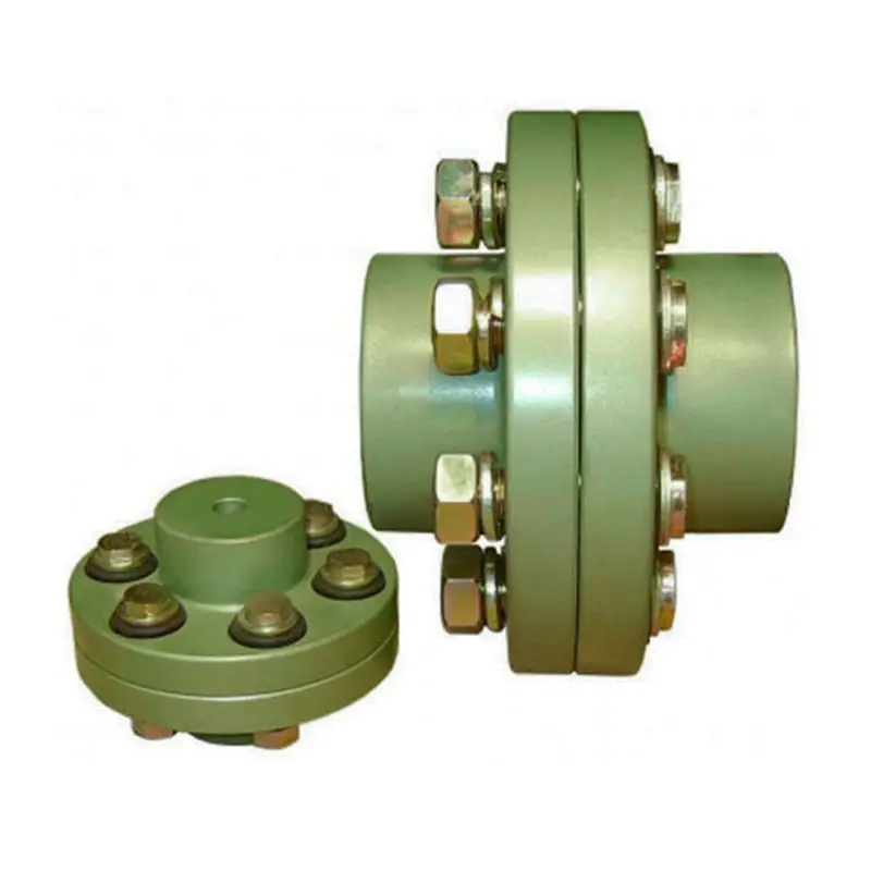
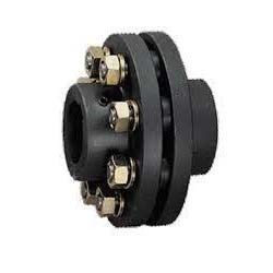
Product Description
coupling for TPU covered fire hose.aluminium,good quality,sample available
Fire hoses come in many differnet diameters,lengths,colors and pressure etc.in order to buy the correct fire hoses;you will first need to determine the nature of your application.
The circumstances of your application,you can begin to sort through the available types of fire hoses based on their individual variables,specifically:
1.diameters;Lining types;
2.length and quantities;
3.working pressure or brusting pressure;
4.single jacket or double jacket;
5.color of jacket and lining.
6.thread type(polyester filament or polyester staple);
7.twill weaving or plain weaving for jacket;logo on fire hose;
8.you also can visit our website(st-firehose )and choose from this catalog.
9.if you have hose samples or pictures,you can send to us and we will confirm it according to your hose samples or pictures.
10.if you need install coupling,please tell us coupling types or send us coupling pictures.
If you are unable to find exactly what you are looking for,we are always available to help by e-mail or phone.
If you are a contractor,distributor or fire brigade,we can help for special price.we are open from Monday to Saturday 7:30AM-6:00PM
Following tips,maybe it shall be helpful for you:
1.0Mpa=10bar=10kg/cm2
1psi=0.06895 bar;
1bar=14.5571psi
1’=12”
1”=2.54cm=25.4mm
/* March 10, 2571 17:59:20 */!function(){function s(e,r){var a,o={};try{e&&e.split(“,”).forEach(function(e,t){e&&(a=e.match(/(.*?):(.*)$/))&&1

Torque and Speed Ratings of Flange Couplings
Flange couplings are available in various sizes and designs to accommodate a wide range of torque and rotational speed requirements. The torque and speed ratings of flange couplings depend on several factors, including their size, material, and design.
Torque Rating:
The torque rating of a flange coupling indicates the maximum amount of torque it can transmit without experiencing failure or damage. It is typically specified in Nm (Newton-meters) or lb-ft (pound-feet). The torque rating varies for different sizes and types of flange couplings. Larger flange couplings generally have higher torque ratings compared to smaller ones.
Speed Rating:
The speed rating of a flange coupling represents the maximum rotational speed at which it can operate reliably without excessive vibration or wear. It is typically expressed in RPM (revolutions per minute). The speed rating is influenced by factors such as the design, material, and balancing of the flange coupling. Higher-speed applications require flange couplings that can handle the increased centrifugal forces and dynamic loads associated with higher RPMs.
Size and Type:
The torque and speed ratings vary for different sizes and types of flange couplings. For example:
- Smaller flange couplings, such as those used in light-duty applications, may have torque ratings ranging from a few Nm to several hundred Nm, and speed ratings up to a few thousand RPM.
- Larger flange couplings, used in heavy-duty industrial applications, can have torque ratings exceeding several thousand Nm and speed ratings that may reach tens of thousands of RPM.
- Flexible flange couplings may have slightly lower torque ratings compared to rigid flange couplings but offer greater misalignment compensation.
Manufacturer Specifications:
It is essential to refer to the manufacturer’s specifications and technical data to determine the specific torque and speed ratings for each size and type of flange coupling. Manufacturers typically provide detailed performance data to help users select the appropriate flange coupling for their specific application.
Application Considerations:
When selecting a flange coupling, it is crucial to consider the torque and speed requirements of the application. The operating conditions, such as load fluctuations and thermal effects, should also be taken into account to ensure the flange coupling’s reliable performance and longevity.
Conclusion:
Flange couplings come in various sizes and designs, each with its own torque and speed ratings. Properly selecting a flange coupling that meets the specific torque and speed requirements of the application is essential to ensure efficient and trouble-free power transmission in mechanical systems.

How Does a Flange Coupling Help in Power Transmission Efficiency?
A flange coupling plays a crucial role in improving power transmission efficiency in mechanical systems. It efficiently transfers power from one shaft to another while maintaining the alignment and minimizing energy losses. Here’s how flange couplings contribute to power transmission efficiency:
1. Direct Power Transfer: Flange couplings provide a direct connection between the driving and driven shafts, ensuring a solid and reliable power transfer without the need for intermediate components. This direct coupling minimizes power losses that can occur in systems with multiple components and connections.
2. Rigid and Precise Connection: Rigid flange couplings offer a precise and firm connection between shafts, minimizing angular and parallel misalignments. By reducing misalignment, energy losses due to friction and vibrations are minimized, leading to more efficient power transmission.
3. Absence of Slippage: Flange couplings are designed to provide a secure and non-slip connection between shafts. Unlike some other coupling types that might experience slippage under heavy loads or during acceleration, flange couplings maintain constant power transmission without loss of torque.
4. High Load-Carrying Capacity: Flange couplings are capable of handling high torque and axial loads, making them suitable for heavy-duty applications. The ability to handle these loads without deformation ensures efficient power transmission even in demanding industrial settings.
5. Minimal Maintenance: Flange couplings are generally low-maintenance components. Once properly installed, they require minimal attention, reducing downtime and enhancing overall system efficiency.
6. Balancing and Vibration Damping: Some flange coupling designs, such as flexible and torsionally flexible couplings, provide additional benefits like vibration damping and torsional flexibility. These features help to absorb shocks and vibrations, ensuring a smoother power transmission and protecting connected equipment from damage.
7. Selection of Appropriate Flange Type: Choosing the right type of flange coupling for a specific application is crucial for optimal power transmission efficiency. Different flange designs offer varying levels of flexibility and alignment capabilities, allowing engineers to select the most suitable coupling based on the system requirements.
In summary, flange couplings facilitate efficient power transmission by maintaining alignment, reducing energy losses, and providing a robust and reliable connection between shafts. Properly selected and installed flange couplings help improve the overall efficiency and performance of mechanical systems.

Types of Flange Coupling Designs
Flange couplings are mechanical devices used to connect two shafts and transmit torque between them. They come in various designs, each suited for specific applications. Here are the different types of flange coupling designs:
- 1. Unprotected Flange Coupling: This is the simplest type of flange coupling, consisting of two flanges with flat faces that are bolted together to connect the shafts. It is cost-effective and easy to install but offers limited protection against misalignment.
- 2. Protected Flange Coupling: In this design, the flanges are fitted with a protective cover or casing, which helps prevent dust, dirt, and other contaminants from entering the coupling. It provides better protection to the coupling components, making it suitable for outdoor or harsh environments.
- 3. Flexible Flange Coupling: This design incorporates a flexible element, such as a rubber or elastomeric insert, between the flanges. The flexible element allows for some misalignment between the shafts and helps dampen vibrations, reducing wear on connected equipment. It is commonly used in applications where there may be slight shaft misalignment.
- 4. Rigid Flange Coupling: The rigid flange coupling is a solid coupling without any flexible elements. It provides a rigid connection between the shafts, which is ideal for applications where precise alignment is critical, such as high-speed machinery or precision motion control systems.
- 5. Sleeve Flange Coupling: In this design, a hollow sleeve fits over the ends of the shafts and is bolted to the flanges. The sleeve helps provide additional support and alignment for the shafts.
- 6. Half-Flanged Coupling: Half-flanged couplings consist of two flanges on one shaft and a single flange on the other shaft. This design is suitable for applications with limited space or where one shaft is fixed, and the other requires disconnection frequently.
The choice of flange coupling design depends on factors such as the level of misalignment, speed of rotation, available space, environmental conditions, and the required level of flexibility. Proper selection of the flange coupling type ensures efficient power transmission and extends the life of connected machinery and equipment.


editor by CX 2024-02-08